Battery Contact Springs: Sizing Force for Vibration, Corrosion and Life
A battery contact spring fails in three ways: too little force (the cell rattles, contact resistance climbs and the device browns out), corrosion (the spring rusts or the plating wears and resistance spikes), and fatigue or set after too few cycles. The design answer is a normal force of roughly 1–5 N for most consumer battery contacts, a spring steel or stainless that holds that force without permanent set, and plating that survives the environment — nickel for economy, gold for low-voltage reliability.
Battery contacts look like the simplest spring job in electronics — a little coiled or stamped spring that touches a cell terminal. But the forces at stake are subtle: the cell must stay seated through drop and vibration, the contact must carry current without heating, and the whole assembly must still work after years of battery changes, humidity and temperature swing. Every field failure I have traced came back to one of three decisions made early: force too low, material wrong for the environment, or life never tested.
Sizing Normal Force: The Vibration and Resistance Trade
Normal force at the contact point does two jobs: it holds the cell mechanically and it keeps contact resistance low electrically. Both need more force than intuition suggests. A spring that merely touches the terminal passes a bench test and fails on a drop table — vibration momentarily separates the contact and the electronics reset. Below roughly 1 N of force, contact resistance becomes unstable and micro-arcs erode the surface. Above 5 N, battery insertion gets stiff and the user complains, and the spring works harder against its own set limit.
| Application | Typical normal force | Notes |
|---|---|---|
| Coin cell holder, low current | 0.5–2 N | Small springs, watch contact resistance |
| AA/AAA battery terminal | 2–5 N | Must survive drop and insertion |
| Power tool / high-current pack | 5–15 N | Contact heating drives force up |
| Spring probe / test contact | 1–3 N | High cycle life dominates |
| Automotive module, vibration | 3–8 N | Vibration keeps force demand high |
Typical ranges for commercial products. Takeaway: size the force from the worst case — highest vibration, highest current, lowest temperature — not the bench case. Then verify the spring delivers that force at its working height with manufacturing tolerances stacked against you, not at nominal. A force spec of "2 N minimum at working height" is worth more than a free-length dimension, because free length is only a proxy for what the contact actually feels.
Material: Force Retention and Corrosion Are Linked
Battery environments are corrosive by nature: humidity, finger salts from battery changes, and outgassing or electrolyte residue in the worst cases. The material must hold its force over the product life while resisting that environment. Carbon spring steel is strong and cheap but rusts; stainless is corrosion-safe but weaker as a spring and less conductive; plated options sit in between.
| Material | Force retention | Corrosion behavior | Conductivity | Typical use |
|---|---|---|---|---|
| Music wire, nickel plated | Good | Needs plating; rusts if plating wears | Good | Economy contacts, dry products |
| Stainless 302/304 | Good | Excellent unplated | Poor | Corrosion-critical, signal current |
| Beryllium copper | Excellent | Good, often plated | Good | Precision, high-cycle, small space |
| Phosphor bronze | Good | Good, tarnishes | Good | Stamped contacts, battery strips |
| Spring steel, gold flashed | Good | Plating-dependent | Good | Low-voltage, low-current reliability |
Takeaway: if the device is low-voltage and low-current — the majority of consumer electronics — corrosion resistance matters more than conductivity, because a few milliohms of oxide is noise compared to a dead contact. For a 3 V circuit, specify plated spring steel or beryllium copper with a real plating thickness; bare music wire belongs in dry, sealed products. Where the spring doubles as a stamped battery strip, the torsion or leaf form often replaces a coil to save height, and the same force-and-set logic applies to the bent section.
Corrosion and Plating: The Resistance Story Over Time
Contact resistance in a battery circuit is a story about the surface over time. Fresh metal measures fine; the question is what the surface looks like after 18 months. Nickel plating on spring steel gives a hard, corrosion-resistant surface at modest cost and is the workhorse for consumer battery contacts. Gold adds low and stable resistance for low-voltage circuits where every milliohm counts. The plating must survive the flexing of the spring — plating that cracks at the bend exposes bare steel, and the corrosion starts exactly where the current flows.
| Plating | Typical thickness | Strength | Weakness |
|---|---|---|---|
| Nickel (electrolytic) | 2–5 µm | Cheap, hard, corrosion barrier | Higher contact resistance than gold |
| Gold flash over nickel | 0.1–0.5 µm Au | Stable low resistance | Thin — wears with repeated insertion |
| Hard gold over nickel | 0.5–1.5 µm Au | Long wear life | Cost |
| Tin | 2–5 µm | Good for power, solderable | Fretting under motion |
| None (stainless) | — | Zero plating cost | High resistance — needs force and wiping |
Takeaway: pair the plating with the expected insertion count. A battery contact inserted a few hundred times over its life tolerates flash gold or nickel; a contact that sees thousands of insertions needs hard gold thickness on the wear track. Whatever the finish, specify the plating on the drawing and test contact resistance after life, not just fresh — the contact spring guide covers the same logic for connectors generally, and it applies double here because batteries come with vibration and salts built in.
Life and Set: Designing the Spring to Still Push at End of Life
Battery contacts take a beating: repeated insertion forces the spring past its working deflection, temperature cycles relax it, and every insertion bends the flexing section. The two life-limiting mechanisms are permanent set (the spring takes a bend and stops pushing) and fatigue (cracks at the bend radius). Design the working stress so the spring stays elastic at maximum insertion deflection — as a rule of thumb keep the maximum bending stress below roughly 60–75% of the material yield for stamped springs, and verify by inserting production samples hundreds of times and re-measuring force. Relaxation and fatigue are different failures with different fixes, and battery contacts suffer both.
The verification loop is short and worth doing on every new contact: measure force at working height on samples, run insertion or deflection cycles to the target life, then measure force retention and contact resistance on the survivors. A contact that loses 30% of its force after 500 insertions will fail in year two even if it passes today. Ask the factory for that data on the sample batch before you approve tooling.
BQUQ designs and builds battery contact springs under ISO9001 in Dongguan, from coiled compression springs to stamped extension and leaf forms, with plating arranged to your spec and batch force testing as standard. Send the drawing with the current, the expected insertion count and the environment to sc@bquq.com or WhatsApp +86 13713157787 — the quotation comes back within 12 working hours, with the force target and material recommendation stated on it.
Email sc@bquq.com or WhatsApp +86 137 1315 7787 with your PDF/DXF/STEP file. An engineer reviews it and replies with price, lead time and DFM notes on working days.
Q: How much force does a battery contact spring really need?
For consumer cells, target 2–5 N at working height so the contact survives drops without intermittent power loss. Higher current or stronger vibration pushes the band up; coin cells with tiny springs can work at 0.5–2 N if resistance is verified.
Q: Should battery contact springs be stainless or plated spring steel?
If the product is low-voltage and sees humidity, stainless avoids the plating-wear failure mode entirely but needs higher force for its resistance. If cost and conductivity dominate, use plated spring steel with nickel or gold at a thickness matched to the insertion count.
Q: Why does my battery contact work new but fail after a year?
Either the spring took a permanent set and lost force, or the plating wore and corrosion raised the resistance. Measure force and resistance on aged samples — a force drop points to set and design stress, a resistance rise points to surface wear and plating.
Q: What is the life target for battery contact springs?
Match it to the product: sealed consumer devices often pass with a few hundred insertions, while chargers, test sockets and tool battery packs need 5,000–50,000 cycles. Define the end point as a force or resistance threshold, then test to it.
Q: Can a battery contact be coiled or stamped — which is better?
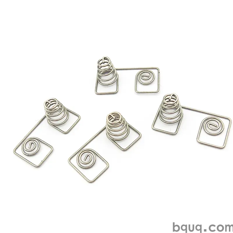
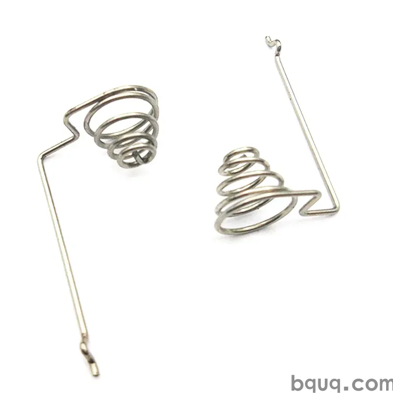
Both work. Coiled contacts (often compression springs) suit round cells and axial force; stamped and formed contacts suit flat packs, low height and integration into a terminal strip. Stamping wins at volume and part integration; coiling wins for round geometry and small quantities without die cost.
Authored by the BQUQ Engineering Team. BQUQ is an ISO9001-certified source factory in Dongguan, China, running CNC machining, metal stamping, custom springs, heat sink and collet lines under one roof. Send drawings to sc@bquq.com or WhatsApp +86 13713157787 for a quote within 12 working hours. www.bquq.com